Trip generation with turnflows allows to model traffic flows in a precise way, for simple, possibly loop-free networks with few internal traffic generation. The general idea is to generate trips and routes for individual vehicles based on road traffic counts. These traffic counts can be performed at junctions. Ideally, the traffic counts should be performed simultaneously at all relevant junctions. However, some edge flows can be derived from other edge flows considering flow preservation lows at nodes.
Basically two types of flows are needed in order to reconstruct the routes in a predefined study area:
- The generating flows FG[a] on all edges a that enter the study area. [1]
- The turn flows FT[a1,a2] for all flows between links a1 and a2 at nodes with more than one exiting edge.
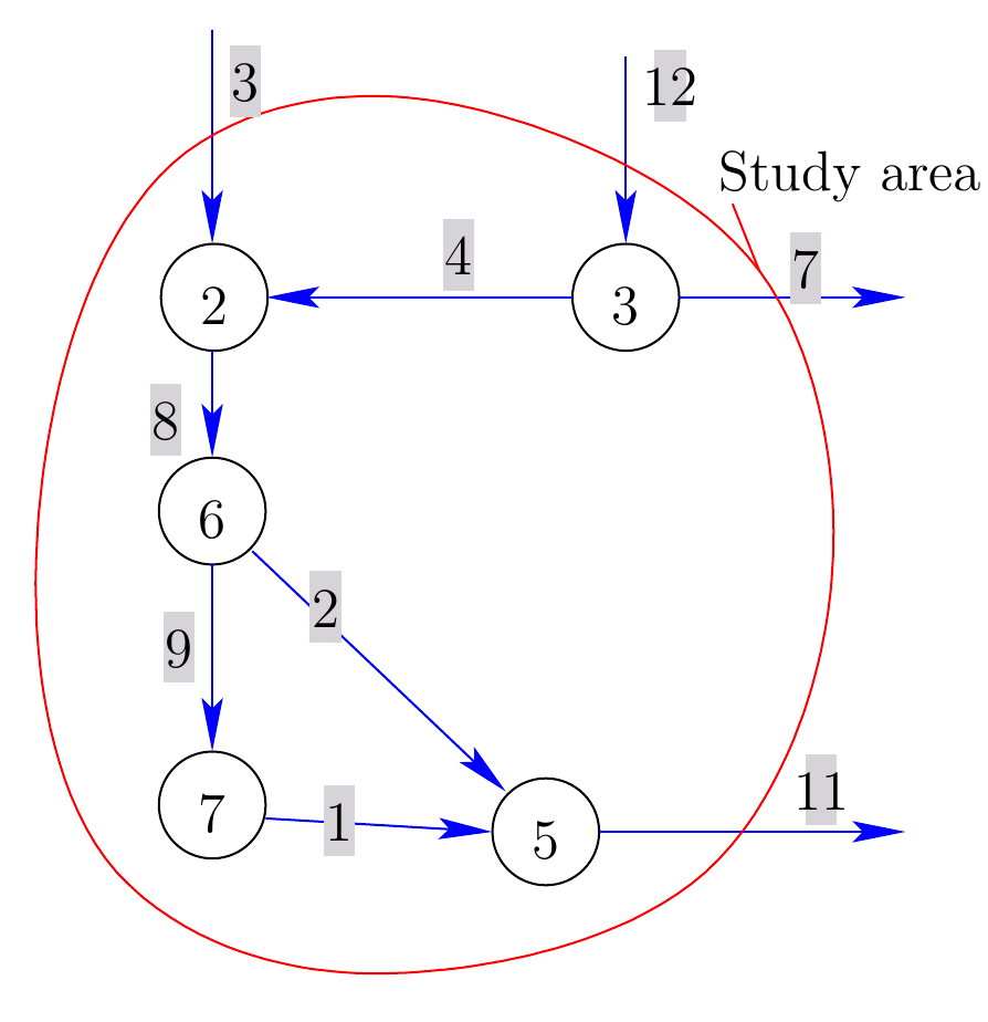
The choice of traffic flows that need to be counted is illustrated by an example network:

Neglecting all traffic generated within the study area, the following flows need to be counted:
- The generating flows FG[3], FG[12] are entering the network.
- The turn flows F[8,9], F[8,2] at node 6 and F[12,4], F[12,7] at node 3. All other nodes have only one exiting edge.
Once the necessary flows are counted for all considered transport modes and time intervals, the trips and routes of all vehicles can be generated with a special router, called JTRouter.
With SUMOPY the route generation with SUMOPY works as follows: First import flows and turnflows from a CSV file by selecting the menu item
Demand>Turnflows>Import turnflows
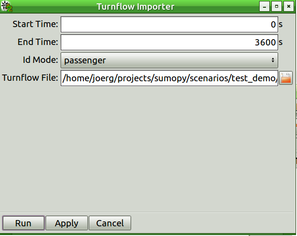
The import turnflows dialog will pop up, as shown below.

This dialog is similar to the OD-flow wizard explained in Sec. Zone to zone demand flows and allows to import traffic counts, and associate them with a time interval and a transport mode.
The Turnflow File to be imported contains the traffic counts of both
flow types, generating flows and turnflows. The turnflow file has the
following format:
<ID1>, <count 1>, <ID11>, <count 11>,  <ID12>, <count 12>, ...
<ID2>, <count 2>, <ID21>, <count 21>,  <ID22>, <count 22>, ...
...
This notation has the following meaning:
<IDa> means the SUMO edge ID of edge a, where edge
a is the edge entering a node.
<IDab> means the SUMO edge ID of edge ab, where edge
ab is the edge outgoing from the node which edge
a enters.
<count a> means the number of vehicles leaving edge a, in
case the edge is generating flows, otherwise this count is zero.
<count ab> means the number of vehicles from edge a
turning into edge b.
All counts in this file refer to the mode and time interval specified in the dialog box.
The turnflow file for the example network shown above, could look like this:
3, 1000
12, 800, 4, 200, 7, 600
8, 0, 9, 800, 2, 400
In this case, the generating flows FG[3]=1000, F[12]=800 and the turn flows FT[8,9] = 800, FT[8,2] = 400 and FT[12,4] = 200, FT[12,7] = 500 for a specific mode and time interval.
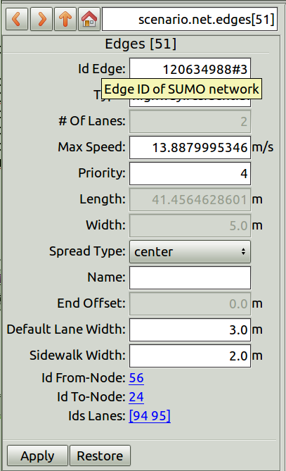
Hint: In order to quickly compile the turnflow file, open a text editor and the SUMOPy window next to each other. In the SUMOPy network editor, deselect lanes, connections and crossings by clicking on the button next to the zoom buttons below the network canvas. Then select the info tool (if not already active) and click on the edges you consider for the turnflow file. The respective edge will be highlighted and you can see all edge attributes in the object browser, as shown below:

From there, copy the SUMO edge ID and paste it into your turnflow text file.
Optionally define destination zones: Within the turnflow demand model destination zones define edges where vehicle routes end. This may be necessary in order to prevent vehicles of making a loop on the network outside the study area and re-entering the study area. Destination zones for turnflows are created in the same way as Traffic assignment Zones in section Zone to zone demand flows.
Generate directly route from flows and turn-flows information by selecting menu item
Demand>Turnflows>Turnflows to routes
This process is using SUMO’s jtrrouter and will generate both trips and routes. The scenario is now ready to be simulated by selecting
Simulation>Sumo>export routes and simulate...
A test file for turnflows is located in
SUMOHOME/tools/contributed/sumopy/testscenario/demo_dem_tf_car.csv
- In addition, traffic flows can also be generated on edges within the study area, but in practice it is difficult to measure those flows because one would need to spot and count only departing vehicles along the roads of the study area. However, for some particular edges with many departing vehicles this may be necessary to do.
